SPINES IN GOLF SHAFTS – 2010
by Bill Day
Over 10 years ago I wrote an article entitled SPINE FINDING – AND WHAT TO DO WITH THEM ONCE YOU FOUND THEM. I'm still getting phone calls and e-mails about it. The article is out of date, and we've learned much more about shafts, spine finding, etc. since that time. I'm retired (again) and out of the golf business, but I still have all my equipment and extra time on my hands – and more knowledge about spines and shafts that I have not shared. So, as a swan song, here goes...........
Golf shafts have improved in the last 10 years – especially graphite golf shafts! 10 years ago it was common for almost all sheet-wrapped graphite shafts to have over one flex of stiffness variation as the shaft was rotated through 360 degrees – and there were reports of over two flexes variation! Nearly all of those shafts were Type 2 shafts, having two resting places in a spinefinder.
Today most of the sheet wrapped shafts have under one flex variation during rotation, and are Type 1 shafts (one resting place) as measured in a spinefinder. Sound like improvement! The Type 2 shafts have less than one flex variation which is an improvement from having two flexes difference when rotating the shaft.
SPINEFINDERS - TOOLS OF THE TRADE:
Before I forget – all testing is done with a bare shaft! Using a grip on the shaft is a big No-No!
Almost all preliminary work on golf shafts is performed with three-bearing spinefinders. These can take many forms, but in all cases have three bearings which allow the shaft to rotate freely. The main version of the spinefinder is a short piece of PVC tubing which houses two bearings. A third bearing is “free” and is used to load (pull down) the tip which allows the shaft to rotate to a stable position. If there is one stable position, it is a “Type 1” shaft. If it has two stable positions (with 180 degree separation) , it is a “Type 2” shaft. If it has more than two resting positions, send it back to the manufacturer.
The “resting” position is very stable and is defined as a N (Natural, Neutral or whatever). The most common term for it is NBP or Natural Bend Position (or Bend Point). It is NOT a spine (S, spine, etc). In a spinefinder an N position is very stable and it takes some force to rotate the shaft out of the position. On the other hand, a spine is the most unstable position you can find – from a spine the shaft can easily rotate either direction. But be very careful! If the shaft is a Type 2 shaft, the spines are found about half-way between the Ns, and are very unstable. But if the shaft is a Type 1 (one resting place) then 180 degrees from that location appears to be a spine - NOT TRUE! It may appear to be a spine because its very unstable, but its really another N!
Please note that the Type of shaft is defined by its performance in a spinefinder – other than that it is almost meaningless since ALL shafts have two S positions and two N positions. But then , what good is a spinefinder? It provides a place to start measuring! That's all. Because spinefinders lie as to the location of S (spines) and N (neutrals). Regardless of the accuracy or sensitivity of the spinefinder, it does not tell the truth about the correct location for shaft positioning or FLO (Flat Line Oscillation). (The NBP is NOT the correct position.)
HOW DO YOU FIND THE CORRECT LOCATION?
There are two ways to find the correct location of Ss and Ns. Both involve “twanging” the shaft (vibrating it) in the preferred direction. I do it “up and down” as opposed to “side to side” because I can get some additional benefit from it. In any case, it involves clamping the butt of the shaft (big end) and “twanging” the tip of the shaft. Anything will work to clamp the butt as long as the butt is not crushed. I use a butt clamp for a frequency counter because I have one and its very convenient (I also have a spin indexer with a three-jawed chuck which works fine, but they're not as common).
The “easy” way to find the S or N location is to use a laser clamped to the tip of the shaft. When the laser is projected on a surface a few feet away, it easy to tell whether the shaft is going up-and-down vertically (FLO or Flat Line Oscillation) or whether the shaft is oscillating in a oval or circle. Keep rotating the shaft in the butt clamp until FLO is achieved, and you will be on an S or N.
You can use a frequency counter to determine the highest frequency (S1) or lowest frequency (N1) but if the counter is capable of only a 1 cpm (cycle per minute) resolution, it may be hard to determine high or low. Some shafts have less than 1 cpm variation as they are rotated through 360 degrees.In this case you can use a combination of laser and frequency to determine FLO – but you may not be able to determine S1 from S2, or N1 from N2 since the Ss and Ns are so close in frequency.
A FEW WORDS ABOUT S AND N (SPINES AND NEUTRAL) IDENT
The S1 spine is defined as the highest frequency (stiffest point) when rotating a shaft through 360 degrees. The S2 spine is defined as the second highest frequency when rotating a shaft through 360 degrees.
The N1 position is defined as the lowest frequency (most flexible) when rotating a shaft through 360 degrees. The N2 position is defined as the second lowest frequency obtained when a shaft is rotated through 360 degrees.
S1 and S2 form a plane through a shaft, since they are 180 degrees apart.
N1 and N2 form a plane through a shaft, since they are 180 degrees apart.
The S plane and the N plane are at 90 degrees from each other.
In all of my testing, the location of the Ss and Ns appear to be consistent and are in the following order: S1 N1 S2 N2. This is when the shaft is rotated clockwise from the butt of the shaft. If you can determine which is which, then you can find the others.
HOW DO YOU FIND WHICH IS WHICH?
If you have a Type 1 shaft (as measured in a 3-bearing spinefinder) then its pretty easy. Use some masking tape near the tip of the shaft and draw a line on the tape at the N (resting place). Use a butt clamp and twang the shaft until you find the point of FLO (flat line oscillation) nearest the mark on the tape (probably about +/- 30 degrees from the mark). That is N1. Mark it with a line on the tape using a different color to distinguish it. (Some people use a mark on the butt of the shaft. I prefer the tip because its easier to use.)
If your have a Type 2 shaft its more difficult. Use the piece of tape as before and mark the two N's (NBPs) with a line. Find the point of FLO for both Ns and mark with a different color. Without a frequency analyzer with 0.1 cycle per minute resolution , it will be nearly impossible to tell the difference between N1 FLO and N2 FLO. Is it important? Well its a plane from N1 t o N2, so it probably doesn't make much difference. Try the frequency analyzer, and if it doesn't work to find the lower frequency of the two you're still going to be very close. (Look at the graphics on the shaft – one position may look better than the other.)
WHERE DO YOU PUT N1 FLO?
Good question. Most clubmakers will put N1 FLO on the face of the club, or “down the fairway”. The other clubmaker option is to put N1 FLO on the back of the club “away from the target”. In either case, the N plane is in the plane and direction of the swing. The stiffest plane (through S1 and S2) is vertical through the clubhead and will try to counter the normal shaft “droop”.
A patented location (SST PURE) is to put S1 on the face of the club and the N plane vertically through the clubhead. I don't like it because the stiffest plane is in the direction of the swing, and the “droop” plane is accentuated by having the most flexible plane in the direction of the shaft droop as the ball is struck. Both work.
TESTING...TESTING
I'm lucky to have the equipment that I do, and the combination is pretty well unique. I have a “spin indexer” that allows me to chuck up the butt of the shaft in a 3-jawed chuck, and rotate the shaft in 1 degree increments throughout 360 degrees (thanks to Bobby Boone). I also have a very sensitive Feel Finder (3-bearing spinefinder) (thanks to Bobby Boone) as well as an inexpensive 3-bearing spinefinder (from Colin Dick). (As I said before, I've found that the sensitivity of the device used to locate the Ns (or NBPs) is really not important because that's not the true location of N1 FLO and N2 FLO.) I also have a ClubScout Frequency Analyzer modified by manufacturer John Kaufman (www.csfa.com) to read in 0.1 cpm increments (which is necessary).
Since I'm retired (again) my shaft inventory is almost non-existent so thanks to Don Johnson for the loan of some additional shafts for test. Testing consisted of shafts ranging from a 9 cpm differential (difference between S1 and N1), and less than 1 cpm differential (which was a steel shaft). I tested primarily sheet-wrapped graphite and steel from various manufacturers, and they all read about the same. Steel shafts are always Type 1. Sheet wrapped graphite shafts may be Type 1 or Type 2. ALL have two N's and two S's.
The NBP (Natural Bend Point) (or Position) is the “resting point” found by a 3-bearing spine finder. It is NOT the position where FLO (Flat Line Oscillation) occurs. In testing several shafts I found about a +/- 19 degree error between the NBP and FLO in Type 1 steel/graphite shafts. In Type 2 shafts (all graphite) there was about a +/-6.5 degree error between NBP and FLO. If you have a Type 2 shaft, there is a good chance that the NBP is close enough to FLO to use the NBP for alignment. Not so for Type 1 shafts!
LASER HOLDER
Its easy to make a laser holder for a small diameter laser (like the kids play laser tag with – not recommended!) Dimensions for the laser I use is about 3/8' diameter by about 2.25 inches long, with a button on the side to turn the laser on/off. To make a holder, take two “pincer” or “spring loaded” clothes pins (steal from your wife) and place them back to back, with one of them upside down. Use a rubber band to tie the two of them together. Strengthen the two ends (clamp part) with more rubber bands to get a firm grip. Clip one about 4 inches from the tip of the shaft. Clip the laser into the other end of the assembly, rotate it so the laser is on, and make sure the clip is firm enough to keep the laser on. Turn it off until you are ready to twang the shaft. Turn the laser on, twang the shaft and note the pattern projected by the laser. Turn it off while adjusting the shaft for more tries for FLO. A set of batteries will last a long time this way – if you don't turn it off between measurements the batteries will last only a week or so.
SEQUENCE OF SHAFT TESTING AND CLUB ASSEMBLY
First, find the orientation of the shaft that you want and note the frequency (or position) at FLO. (In other words, do spine testing first). As far as a tip weight is concerned, you can use a symmetrical tip weight (Sliding Tip Weight, Drill Chuck, etc.) or you can use the club head. If you use the club head, secure it to the shaft with a shim of some type (rubber band, fishing line, plastic bag, etc.). If you don't get it tight, the weight may “rattle” indicating it is not tight enough. Don't worry about which way a club head is turned – John Kaufman has shown that an offset weight makes no difference is locating FLO.
Measure the frequency (or determine the stiffness you desire) and tip and butt trim the club as necessary.
Glue it together with some shafting epoxy (not from a hardware store) and you're ready to align the shaft. While the epoxy is fresh, with the alignment mark on the tip of the shaft, place the head under the bench top (I have a 2 x 4 there) and square the head. Rotate the shaft until the mark is directly “UP”, and the rotation is correct. For a different look in graphics, place the head on top of the bench and rotate the shaft until the mark in directly “UP”. Very carefully set the assembly down without rotating the shaft or head.
TEST RESULTS
I mentioned that I had tested a steel shaft in 1 degree increments through 360 degrees (Figure 1). The shaft had only 1 cpm difference (between 299.7 and 298.7 cpm). Since there were only 10 possible readings between these frequencies it was very difficult to read correctly. Some of the plot readings appear as straight horizontal lines (repeats of a frequency). It took almost 3 days, with repeated “twanging” to insure a correct reading. I found out two important things: 1) the shaft had two Ss and two Ns and 2) with an error of more than 10 degrees, the shaft started ”ovaling”. At times this “one cpm shaft” ovaled so violently that it proved to me that its necessary to align ALL shafts regardless of frequency differential.
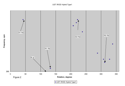
The second plot (Figure 2) shows a UST IROD shaft that is a Type 1 shaft according to the spinefinder. For some reason the computer glitched on the vertical scale, but the S1 frequency is 269.7 cpm. The NBP is marked as Nsf and is about 115 degrees, while N1 FLO is at 130 degrees. Note that N2 FLO is about 310 degrees, 180 degrees from N1 FLO.
Figure 3 is a Type 2 shaft noted a Calients #3, and is over a 7 cpm differential shaft. More testing was done on this shaft to find out is there was a
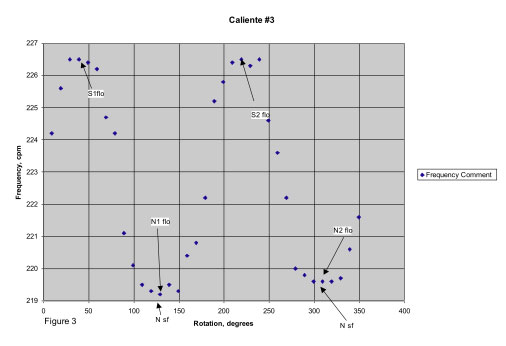
difference between the “width” of the S peaks and the N valleys. They both appear to be the same, with no preference for either one in terms of shaft orientation. With a large differential between S and N, I would favor placing the N “down the fairway” because it would place the S plane to minimize the “droop” in the shaft during the swing. With a 1 or 2 cpm difference there appears to be no preference for orientation.
I have heard that one orientation is best for distance, while the other is best for accuracy. Maybe, but I've seen no studies to confirm that one orientation is better or worse for anything.
Bill Day is retired (again) from clubmaking after a career in electronic engineering. It really was more fun making clubs! For questions, my e-mail address is billday@q.com .
Return to Clubmaker Online Resource Page